© 2014 Foundation Supportworks
®
,
Inc.
All Rights Reserved
p 7
Chapter 2
Helical Foundation Systems
CHAPTER 2
HELICAL FOUNDATION SYSTEMS
2.3 – Helical Foundation
System Components
2.3.1 – Helix Plates
The initial installation of a helical pile is performed
by applying downward force (crowd) and rotating
the pile into the earth via the helix plates. Once
the helix plates penetrate to a depth of about
two to three feet, the piles generally require less
crowd and installation is accomplished mostly
by the downward force generated from the helix
plates, similar to the effect of turning a screw
into a block of wood. Therefore, the helix plate
performs a vital role in providing the downward
force or thrust needed to advance the pile to
the bearing depth. The helix plate geometry
further affects the rate of penetration, soil
disturbance and torque to capacity correlation.
The consequences of a poorly-formed helix are
twofold; (1) the helix plate severely disturbs the
soil with an augering effect which (2) directly
results in more movement upon loading than a
pile with well-formed helices. The differences
between a well-formed helix and poorly-formed
helix are visually obvious and are shown in
Figure 2.3.1.a
.
A true helix shape can be described as a three-
dimensional curve that travels along and sweeps
around an axis where any radial line remains
perpendicular to that axis.
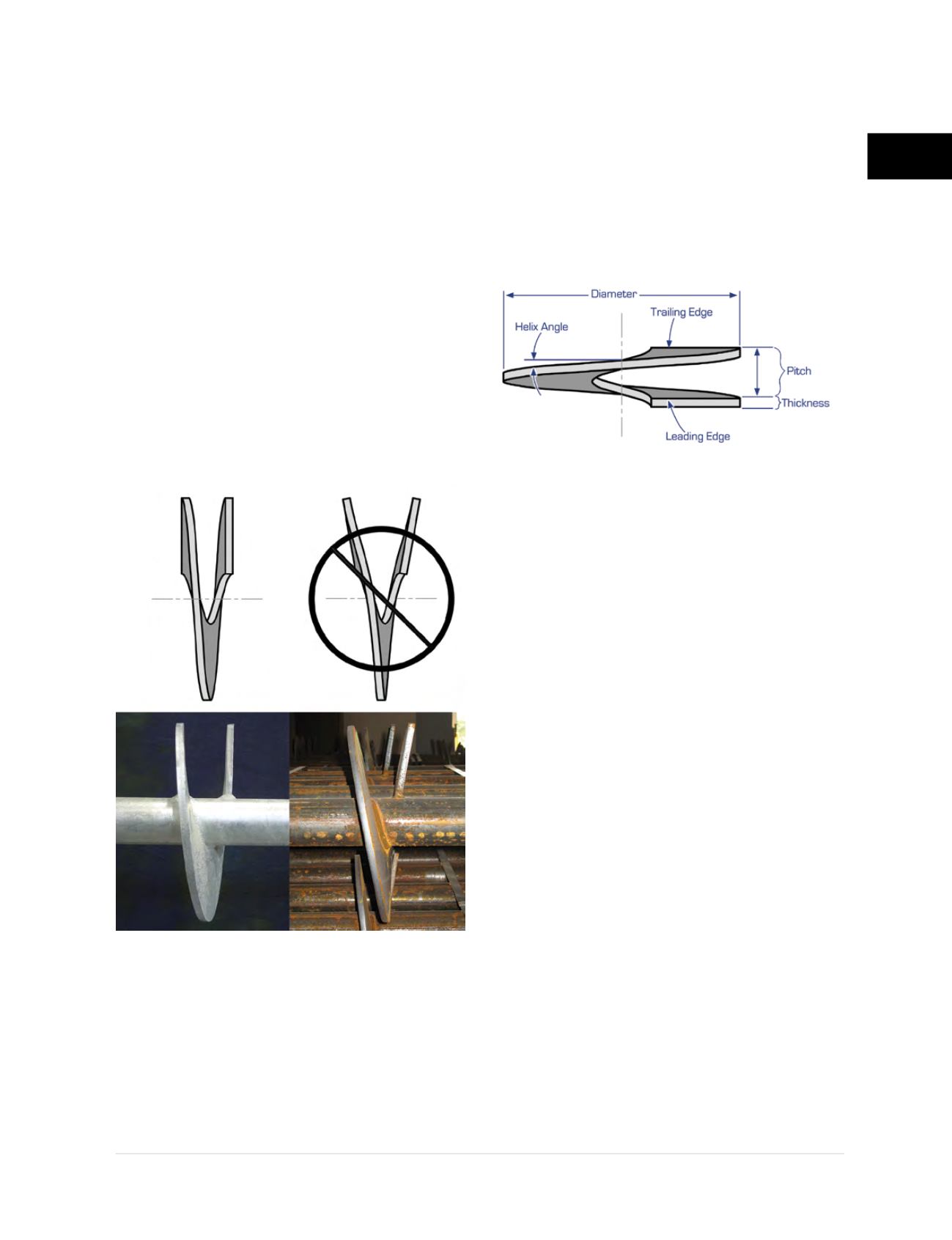
A helix plate is further defined by geometric
parameters including diameter, thickness, pitch,
helix angle and edge geometry
(Figure 2.3.1.b)
.
Helix plate diameters can vary from 6 to 16
inches for most commonly used shaft sizes. The
majority of helix plates have thicknesses of either
3/8
or
½
inch, however, thicker plates are used for
larger diameter piles. The pitch is the distance
or separation between the leading and trailing
edges and controls the depth of installation per
revolution of the helix plate. The helix angle is
the blade angle formed relative to the shaft and
will vary within the blade for any given radius.
The edge geometry refers both to the perimeter
geometry of the helix and the shape of the
leading and trailing edges. Most helix flights are
manufactured with a perimeter geometry that is
generally circular. The leading edge can have
varying cuts and shapes including blunt (flat),
sharpened, standard cut, V-style cut, etc. to
provide options for changing soil conditions. The
trailing edge is generally a standard cut, blunt or
sharpened, and has no effect on installation in
varying soils.
A helix plate is formed by cold pressing the
steel plate with matching machined dies. Both
the shape of the die and the amount of applied
Figure 2.3.1.a
Incorrect
Correct
Figure 2.3.1.b
Helix Plate Geometry


