© 2014 Foundation Supportworks
®
,
Inc.
All Rights Reserved
p 29
Chapter 2
Helical Foundation Systems
CHAPTER 2
HELICAL FOUNDATION SYSTEMS
2.8 Helical Tiebacks
Helical anchors/tiebacks are commonly used in
tension applications to provide either temporary
or permanent lateral or tie-down support for
applications including:
• Earth retention systems such as concrete
retaining walls, soldier pile and timber lagging,
and sheet piling
(Figures 2.8.a1 and 2.8.a2)
• Seismic loading restraint for foundation uplift
and lateral support systems
• Guy anchor support for power line and
communication towers
• Seawalls and marine bulkhead support
(Figure 2.8.b)
Helical tiebacks are manufactured with similar
helix plate sizes and helix spacing as helical
piles installed vertically to support foundation
loads. Tiebacks differ from helical piles in that
they are typically installed in a horizontal to
45-degree downward from horizontal orientation
to laterally support the tops of earth retaining
structures. Helix plates are typically limited to
the lead section or the lead and first extension
of the tieback. The helix plate design depends
on the soil strength parameters and the required
working capacity. Multi-helix leads generally
consist of increasing plate sizes from the tip.
Helical tiebacks may consist of either hollow
round shaft or solid square shaft, although
square is more common due to its socket-
and-pin style coupling (quicker and easier to
connect) and the ability to penetrate further into
the soil with a similar installation torque than a
comparably-sized round shaft. The end of the
shaft is typically coupled to an adaptor that
transitions the shaft to threaded rod. Refer back
to
Figure 2.3.3.d
.
Both the individual bearing method and the
cylindrical shear method are appropriate for
determining helical tieback capacity. The torque
correlation method is commonly used to verify
capacity during tieback installation. These
methods are discussed in Section 2.7.
Helical tiebacks are often used to stabilize
existing earth retaining structures that have
experienced excessive movement; i.e., walls
Figure 2.8.a1
Rendering of helical tieback
installation for soldier pile and timber lagging wall
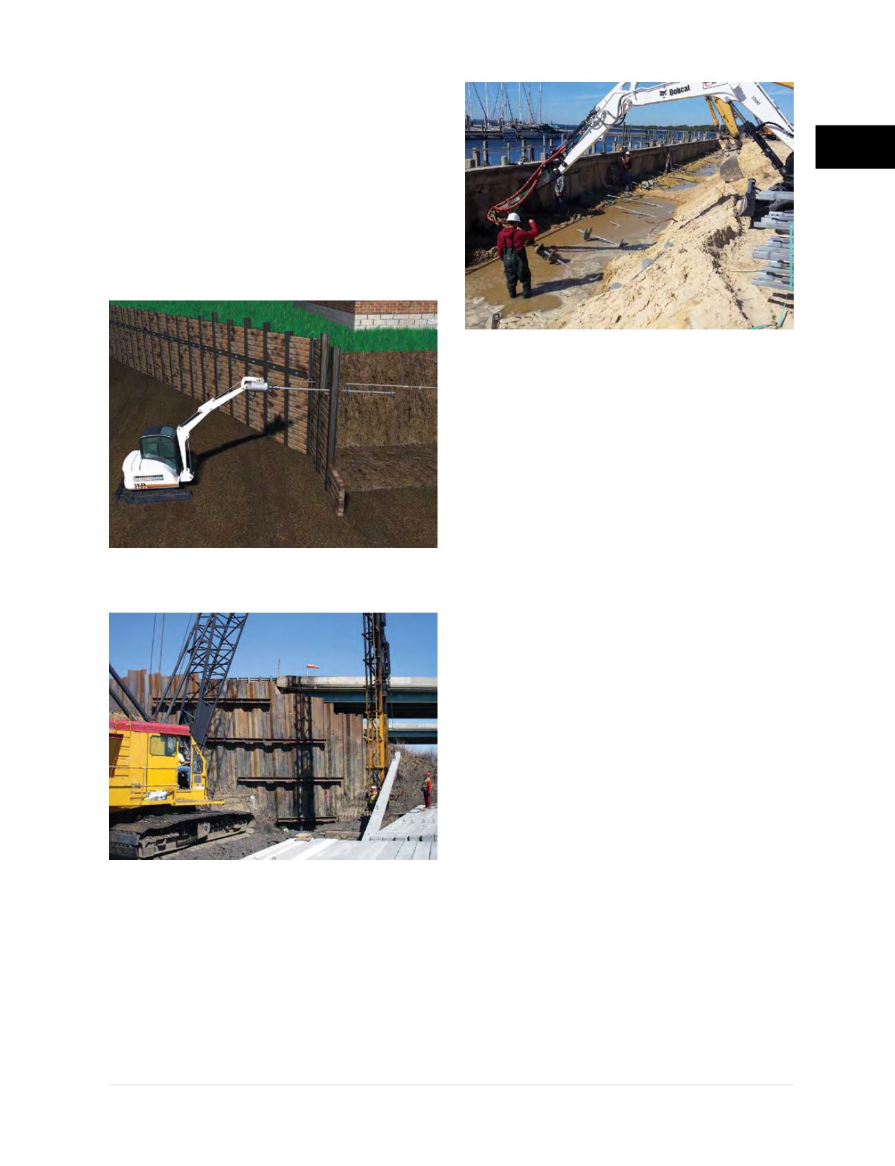
Figure 2.8.b
Helical tiebacks
stabilize marina seawall
Figure 2.8.a2
Multi-tier helical tieback
installation to support sheet pile wall


