© 2014 Foundation Supportworks
®
,
Inc.
All Rights Reserved
p 52
Chapter 2
Helical Foundation Systems
CHAPTER 2
HELICAL FOUNDATION SYSTEMS
not provide an accurate or reliable indication
of torque and should not be used solely as a
measure or estimate of applied torque.
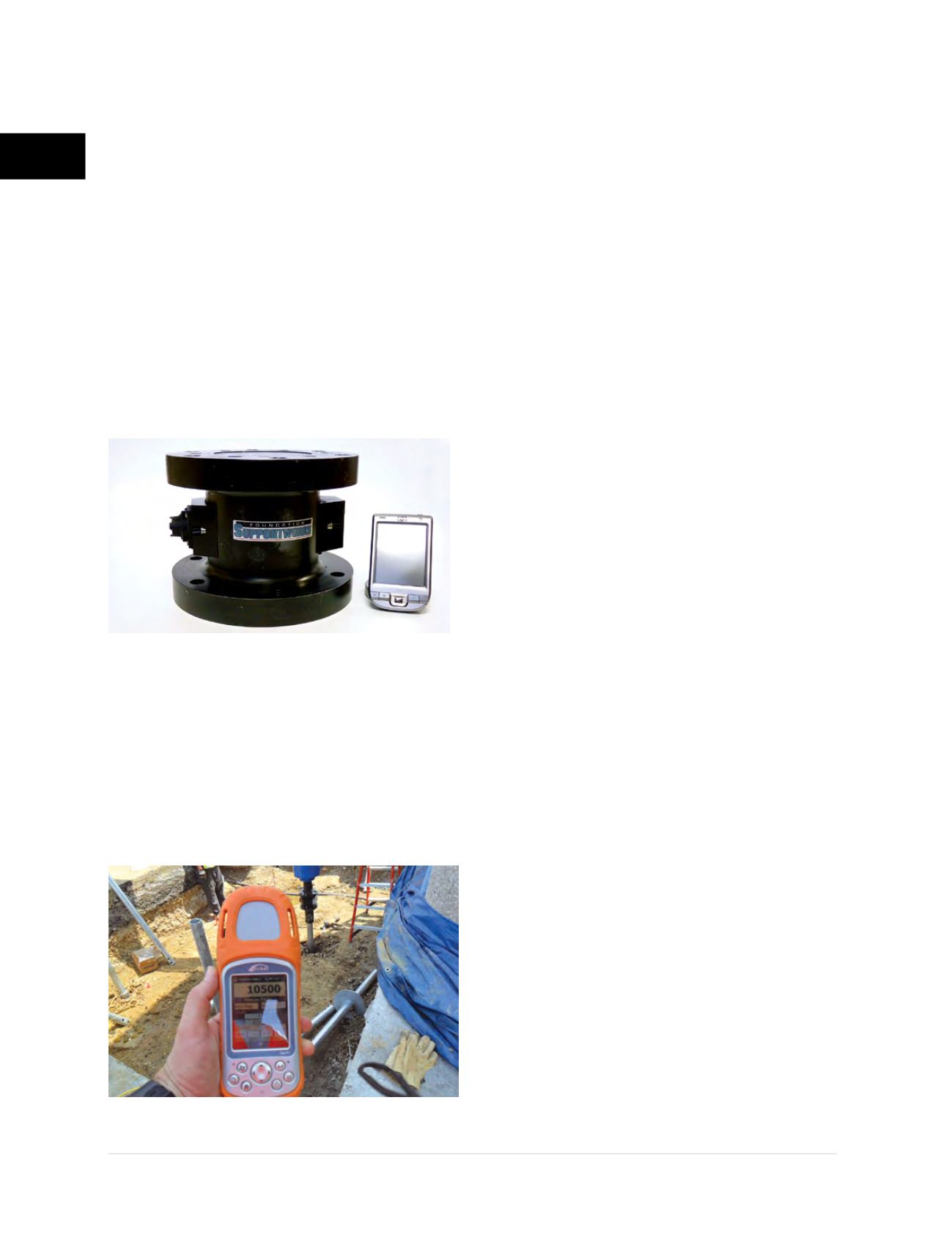
Electronic torque transducers
such as the Pro-
Dig intelli-Tork
®
are placed in line with the tool
string. Torque is a true real time measurement and
is generated continually during the installation of
a helical pile or tieback. The intelli-Tork
(Figures
2.12.2.3.e1 and 2.12.2.3.e2)
measures the torque
applied between two flanges and transmits the
torque reading to a hand held unit for display
and logging. A built in torque sensor within the
housing of the flanged instrument transfers data
via blue tooth wireless technology to the PDA
system. The PDA based system and software
provide a remote visual indication of the torque
during the installation. Software provided with the
instrument has the ability to log the torque, depth
and installation angle. Torque transducers can be
re-calibrated as needed to ensure accuracy. In
turn, a properly calibrated torque transducer can
be used to calibrate analog gauge systems relative
to differential pressure.
2.12.3 Installation Guidelines
2.12.3.1 New Construction
Installing the Lead Section:
• Align the lead section with the product adaptor
and install the temporary hitch pins or bolts.
• Position the installation equipment and pile
directly over the marked location.
• Apply a small amount of crowd to seat the pile
shaft tip into the soil.
• Use a level or digital gauge to plumb or set the
installation angle (batter) of the pile shaft.
• Advance the pile in a continuous even manner,
making periodic adjustments to maintain
alignment throughout the installation. Record
torque as required by project specifications
or as dictated by changing soil conditions.
Although the final installation torque is
arguably the most critical, it is good practice
to record pressure or torque during the entire
installation. This allows for development of a
relative soil strength profile with depth. The
interval of readings is often dictated by the soil
variability; i.e., more readings should be taken
in heterogeneous soils and fewer readings are
required in uniform, homogeneous soils. At a
minimum, record torque for every lead section
and extension.
• Terminate installation of the lead section before
the product adaptor penetrates the soil.
• Remove the hitch pins or bolts and carefully
remove and raise the drive head.
Installing Extension Sections:
• Place the first extension on top of the buried
lead. Align the coupler bolt holes with the bolt
holes of the lead section. Use a spud wrench
if necessary.
• Install coupler bolts taking care not to
damage threads. Tighten nuts to snug
condition
(Figure 2.12.3.1.a)
.
Figure 2.12.2.3.e1
Electronic torque transducer
Figure 2.12.2.3.e2
Torque transducer providing direct reading of
torque for helical pile project at Reagan National Airport


