© 2014 Foundation Supportworks
®
,
Inc.
All Rights Reserved
p 55
Chapter 2
Helical Foundation Systems
CHAPTER 2
HELICAL FOUNDATION SYSTEMS
• Advance lead section and extensions to design
depth and minimum torque requirements.
• Record pressure or torque readings. Although
the final installation torque is arguably the most
critical, it is good practice to record pressure or
torque during the entire installation. This allows
for development of a relative soil strength
profile with depth. The interval of readings is
often dictated by the soil variability; i.e., more
readings should be taken in heterogeneous
soils and fewer readings are required in uniform,
homogeneous soils. At a minimum, record
torque for every lead section and extension.
• If necessary, cut the last extension shaft to
an elevation approx. 13 inches above bottom
of footing.
• Ideally, the last coupler on the helical pile shall
be at least 23 inches below the bottom of
the footing to allow installation of the 30-inch
external sleeve.
Installation of Underpinning/Retrofit Bracket:
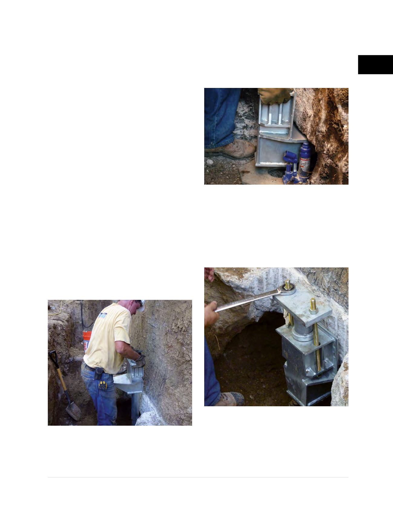
• Place external sleeve through bracket.
• Lower bracket and external sleeve assembly
over the pier shaft with bracket bearing
plate facing away from the footing
(Figure
2.12.3.2.d)
.
• Rotate the bracket body 180 degrees toward
the footing.
• Raise bracket to the footing and hold the
bracket in place while attaching the thread
rods and cap plate. A bracket RAYser
™
is a
great tool to hold the bracket in place during
this operation
(Figure 2.12.3.2.e)
.
• Tap the external sleeve down until the top
flange rests on the bracket.
• Install the cap plate and all thread rods and
tighten nuts to snug the bracket to the bottom
of the footing
(Figure 2.12.3.2.f)
.
• Remove bracket RAYser
™
, backfill and
compact soil up to the bottom of the bracket.
Figure 2.12.3.2.d
Lower assembly over pile shaft
Figure 2.12.3.2.e
Bracket RAYser
™
Figure 2.12.3.2.f
Install cap plate and rods


